LOAD PATH / MOUNTING / CALIBRATION
A stable measurement starts below the sensor.
Single-ended versus double-ended selection, shear-web working principles and the mounting checks that matter for tanks, hoppers and weighbridges.
Single-ended vs double-ended: two different support arrangements
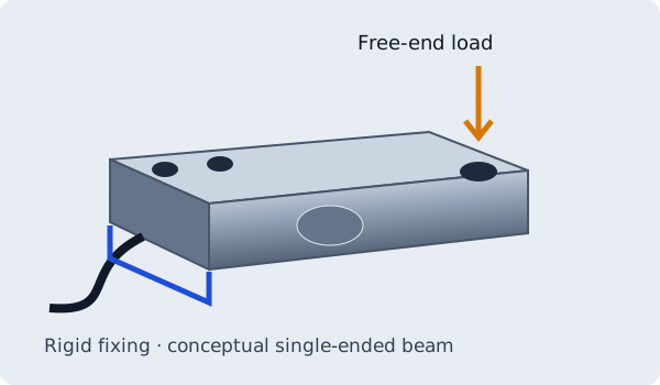
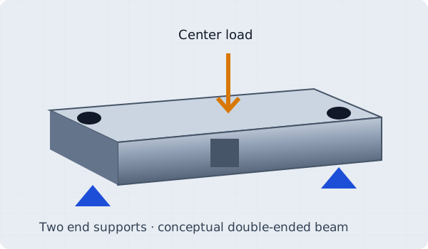
A single-ended beam is fixed at one end; a double-ended beam is supported at both ends and loaded centrally. Select by load introduction, constraints and available mounting geometry. Neither architecture is the only valid solution for every weighbridge or silo.
How the shear web measures load
A locally reduced web develops shear strain under the applied force. Strain gauges arranged near ±45° to the beam axis sense the associated principal strains and form a Wheatstone bridge. The small differential output is proportional to excitation, expressed as mV/V.
The shear arrangement can reduce sensitivity to load-position changes within its specified loading zone. It does not make the cell immune to bending moments, side force, bad mounting or arbitrary load points.
Three checks for tank and reactor installations
- Restrain uplift and horizontal movement. Specify appropriate anti-lift modules and horizontal restraints for wind, seismic, agitation and pipe forces. Hardware ratings and thermal expansion must be reviewed for the vessel.
- Keep welding current out of the sensing element. Prefer welding before installing cells. Follow the manufacturer’s isolation procedure and use a suitable bypass bonding path; never rely on the load cell as an electrical return. Disconnect sensitive electronics as specified.
- Reduce parasitic pipe forces. Use suitable flexible connections or engineered pipe supports. Review all inlet, outlet, vent and service connections through the expected temperature and movement range.
Cell capacity is more than total weight ÷ support count.
Evaluate maximum gross load, uneven load distribution, impact, overload, restraint forces and maintenance conditions. Select a load cell and module using the worst credible reaction at each support, with the project engineer’s design criteria.
Commission the complete signal chain.
Check a flat mounting surface, bolt grade and specified torque, load direction, clearance, load introduction and cable protection. Verify excitation and wire functions before energizing. Adjust corners with an appropriate summing box and calibrate the installed system using traceable reference loads.
OIML / NTEP approval and ingress protection answer different questions.
OIML R60 and NTEP concern weighing performance and legal metrology requirements; they do not standardize mechanical hole patterns. Confirm the exact approval and allowed use. IP68 immersion conditions and IP69K washdown qualification also require model-specific evidence; one rating does not automatically include the other.
Download the configuration checklistDIMENSIONS. LOAD PATH. SIGNAL.
Get the complete weighing kit specified.
Send capacity per cell, support count, thread standard and your existing drawing.